Overview
In this sample, we are going to use a single service forwarder to transfer a port from the local connector to a remote connector, and, over top of that, run a web socket UDP tunnel, and, over top of that, run a Wireguard VPN. This will provide layer 3 adjacency. We will use wstunnel to facilitate. We will use the Agilicus connector to facilitate the inbound/outbound connectivity, and, authenticate via a Service Account for always-on operation.
For the sample, we assume the main site and the remote site(s) each have a device running Linux (the sample is for Debian or Ubuntu). We also assume the sites have non-overlapping IP (avoiding the need for NAT in either of the directions).
High Level Steps
- Create a connector on each of ‘Main site’ and ‘Remote site’
- Create a network on Remote Site, using destination 127.0.0.1, port 4443
- Create a service forwarder, via ‘Main Site’, listening on 127.0.0.1 port 4443, destination the network created above
- Run ‘wstunnel’ on Remote site, listening for connections on 127.0.01 4443
- Run ‘wstunnel’ on Main site, sending connections to 127.0.0.1, port 4443
- Run wireguard on each of the sites, using wstunnel as the source/sink
Agilicus Connector & Network Setup
In this example, we assume your domain is connect.example.org. This you would use https://admin.connect.example.org for administration. We assume you are going to have two sites connected, ‘main’, and ‘remote-1’ (you can later add more remotes).
Main: Connector & Service Account & Application Setup & SSH
On the ‘main’ site, install an Agilicus Connector.
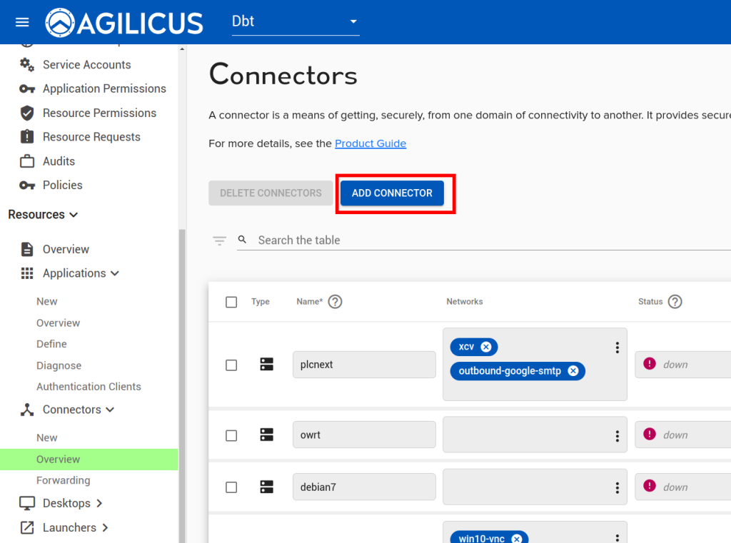
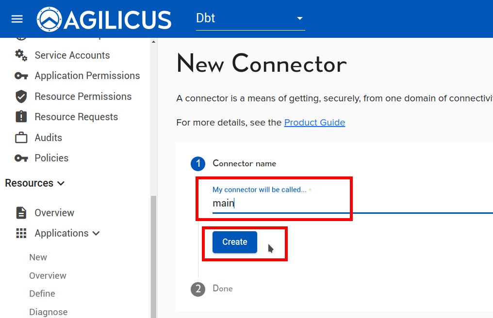
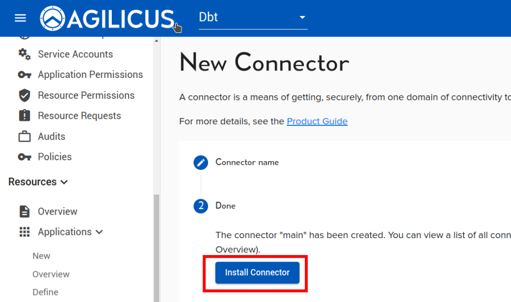
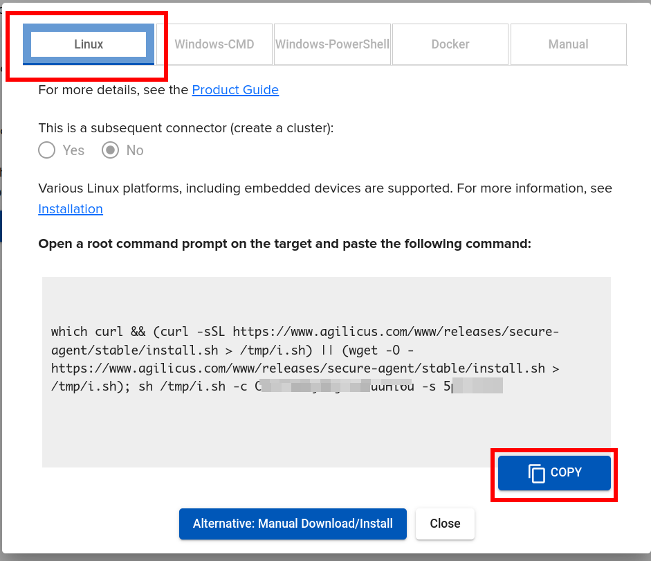
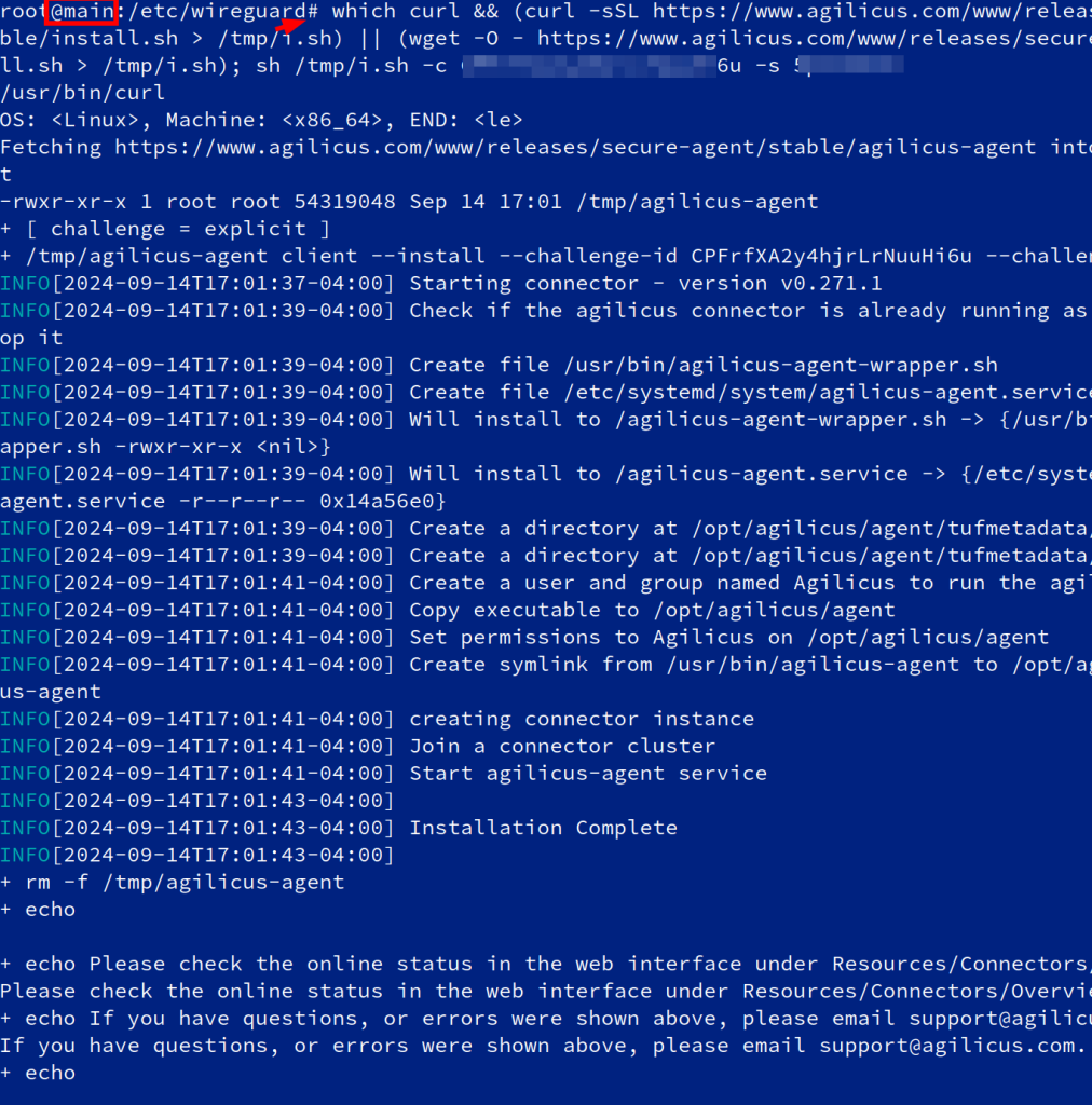
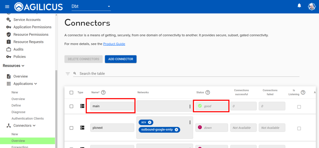
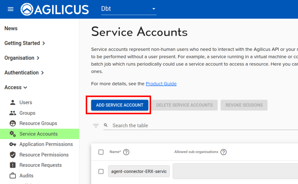
Now we will create a ‘application’ to use this Connector. First, we will create a Service Account, a special system user that will have always-on permission to use it.
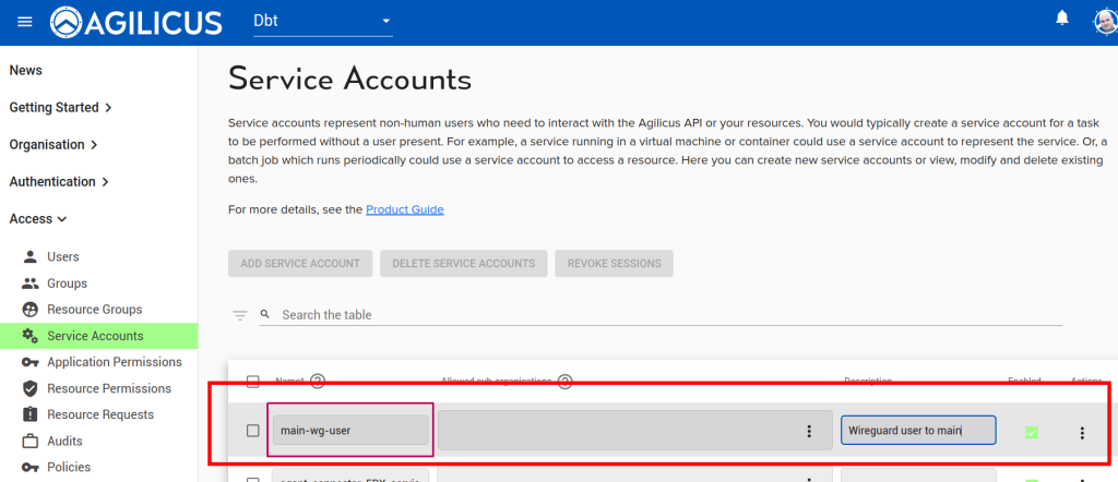
Now, we will create an “application’ to use this Connector.
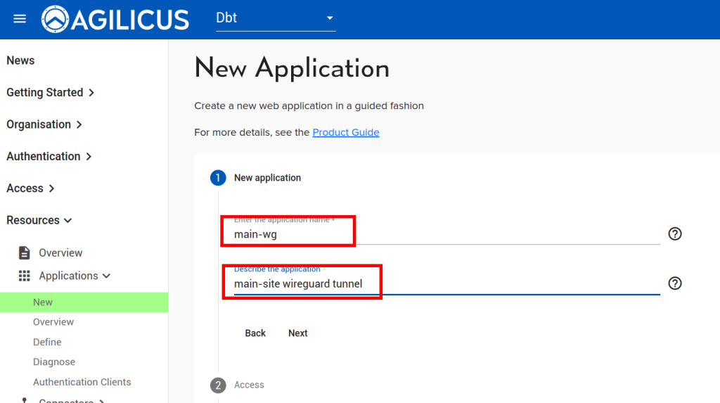
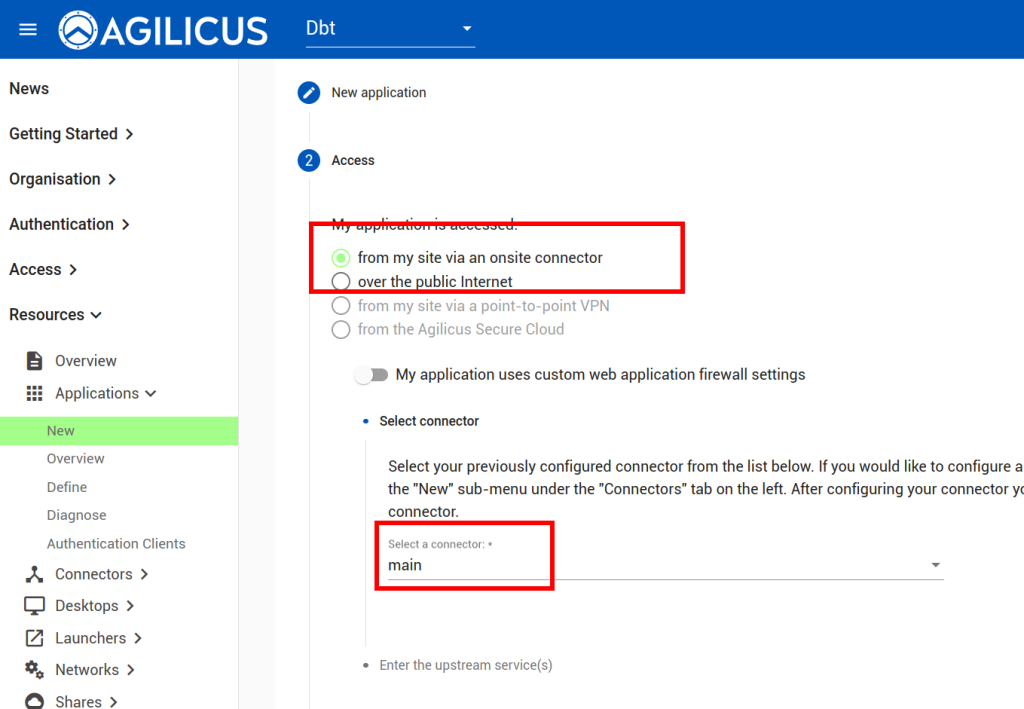
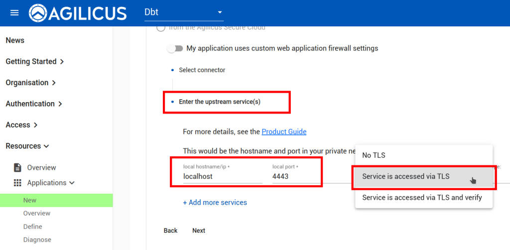
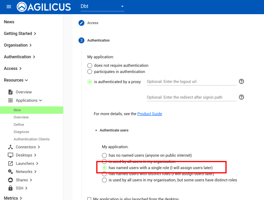
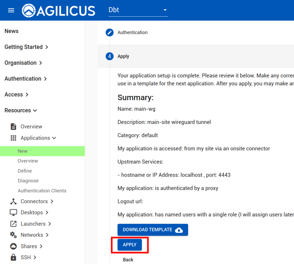
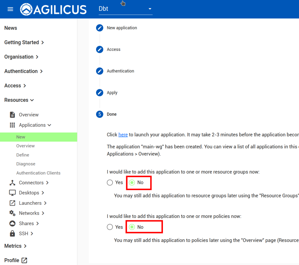
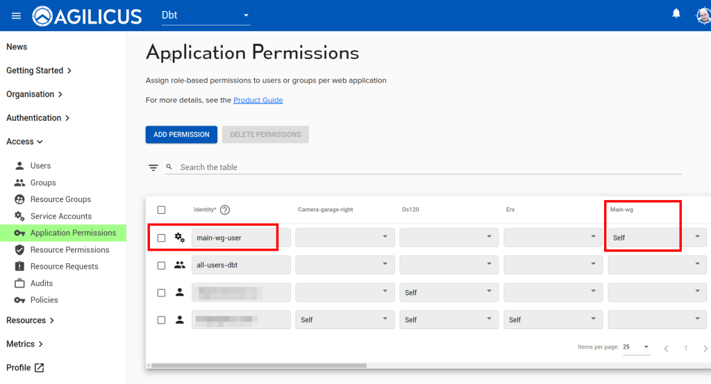
Now we will assign permissions to the Service Account we created above:
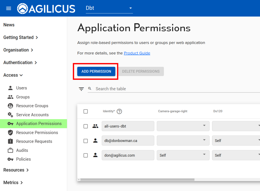
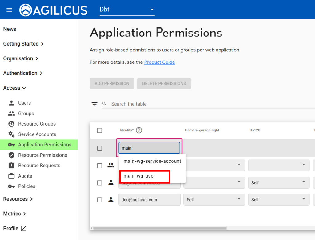
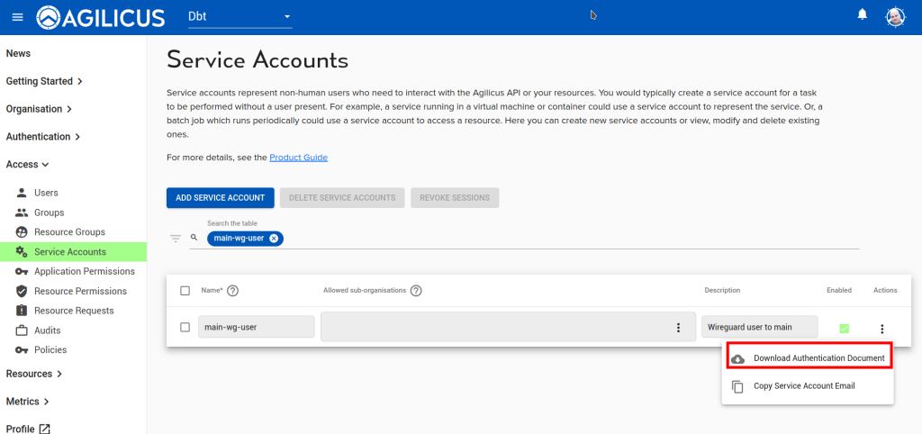
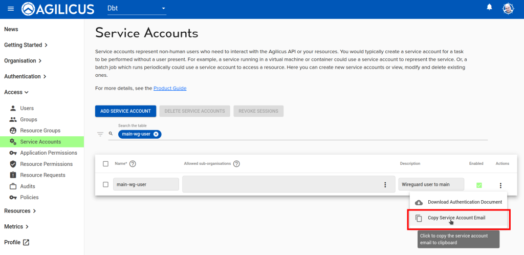
Download and save the ‘Authentication Document’ for this Service Account, we will use it below. Also, copy and save the service account email, we will use that below.
Now, let us setup SSH so we can remotely administer this device:
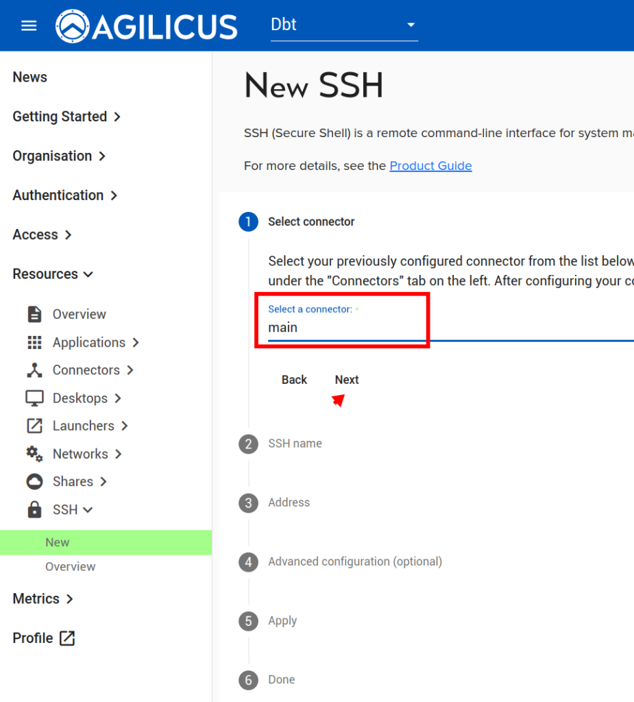
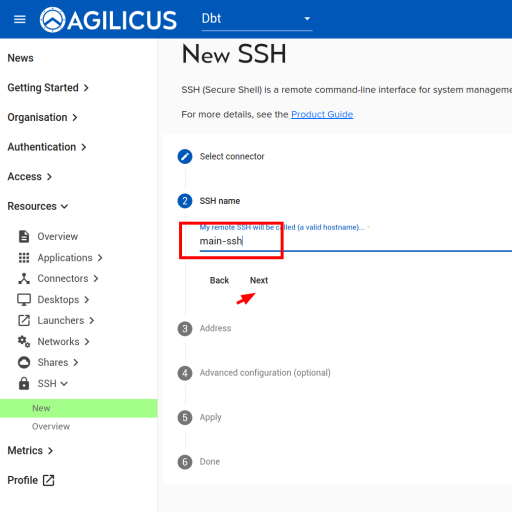
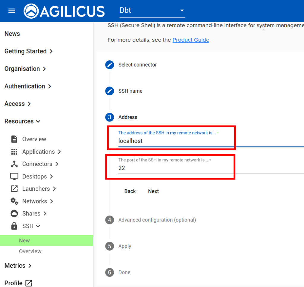
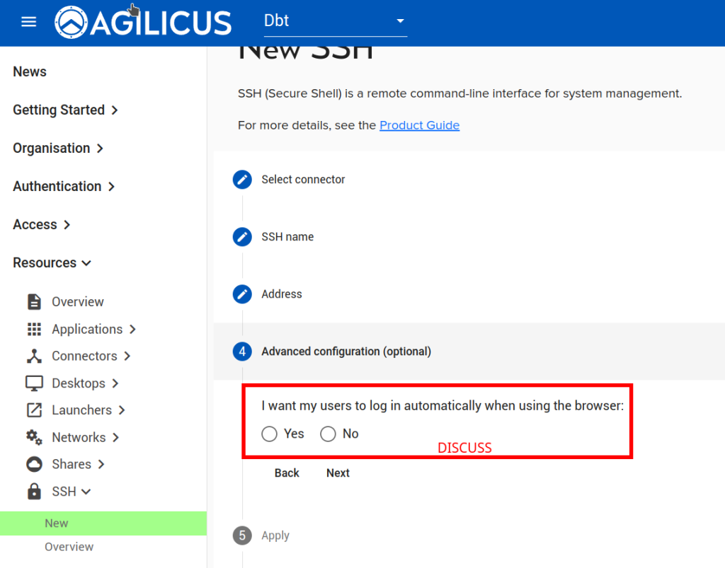
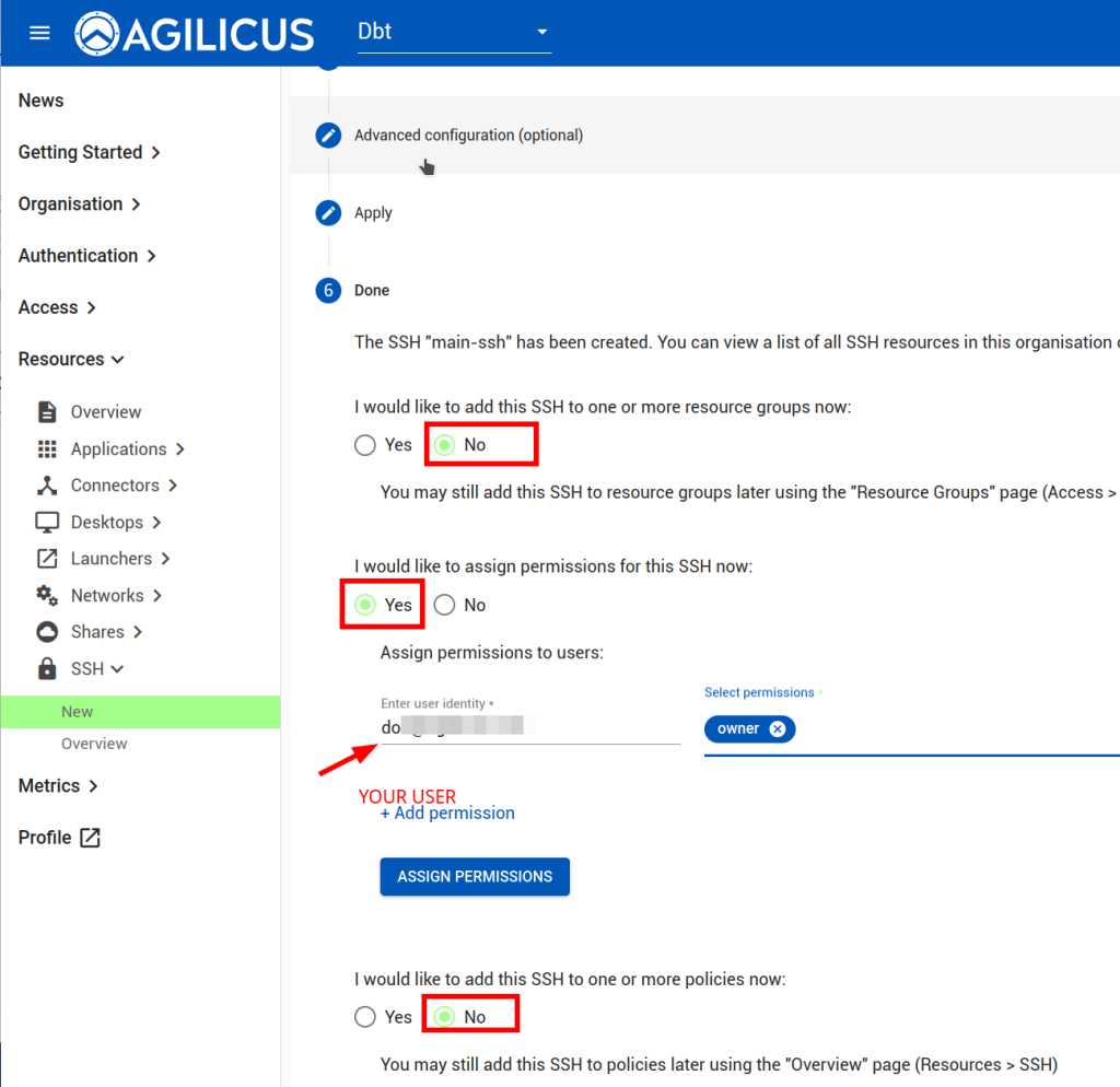
NOTE: feel free to modify the options. The ‘DISCUSS’ on users auto-signing in, this may be a convenient way to use a browser-based sign in without giving users the password of the device.
At this stage we are complete setting up ‘main’.
Remote: Connector & SSH
Install the connector as above in main, switching the connector name to remote-1.
Setup SSH as above in ‘main’, switching the connector to remote-1 and the SSH name.
Checks
If we examine the connector screen, we can see that each of our new connectors exists, and has SSH bound to it, as well as ‘main’ has the wireguard service from the application we created:
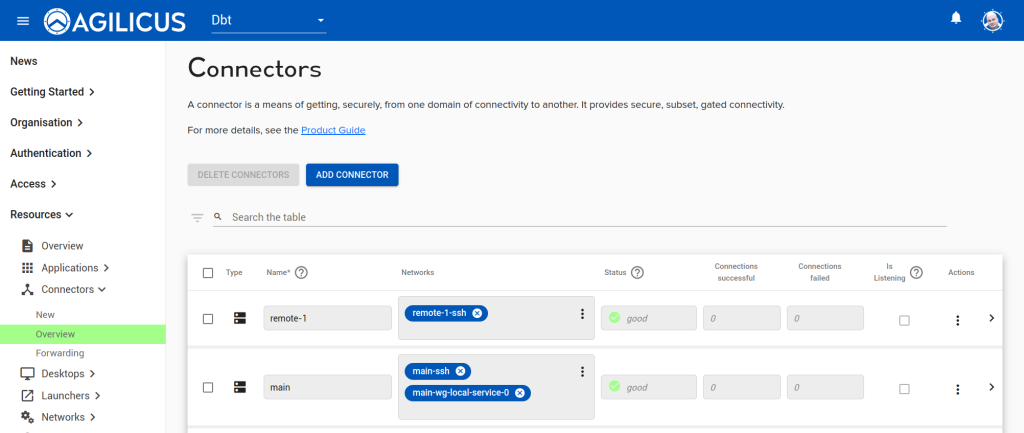
We can also check by opening https://profile.connect.example.org and hitting refresh, we should see an SSH icon for each, and, if selected, should be able to sign-in. NOTE: we recommend creating an SSH key and using the native integration for a more seamless and secure experience.
Linux Setup
We now have some Linux-specific setup to do, outside the scope of Agilicus AnyX. This is to install a site-to-site connectivity agent called ‘wireguard’ and a WebSocket tunnel to facilitate it.
Install Wireguard: Main
On the ‘main’ site Linux device, run the following commands as root (e.g. run sudo su - first):
apt-get update
apt-get install -y wireguard wireguard-tools
mkdir -p /etc/wireguard
chmod 700 /etc/wireguard
cd /etc/wireguard
wg genkey | tee wg.key | wg pubkey > wg.pub
chmod 600 /etc/wireguard/*.key
KEY=$(cat wg.key)
cat <<EOF > wg0.conf
[Interface]
Address = 10.8.0.1/24
ListenPort = 51820
SaveConfig = false
PostUp = iptables -A FORWARD -i wg0 -j ACCEPT
PostDown = iptables -D FORWARD -i wg0 -j ACCEPT
PrivateKey = $KEY
PostUp = iptables -A FORWARD -i wg0 -j ACCEPT
PostDown = iptables -D FORWARD -i wg0 -j ACCEPT

EOF

echo -e "\nCopy below line to remote machine:"
echo -e "MAIN_KEY=$(cat wg.pub)\n"
Install Wireguard: Remote
On the ‘remote’ site Linux device, run the following commands as root (e.g. run sudo su - first):
<<PASTE MAIN_KEY=... LINE FROM ABOVE>>
MAIN_SUBNET=172.16.30.0/24
apt-get update
apt-get install -y wireguard wireguard-tools
mkdir -p /etc/wireguard
chmod 700 /etc/wireguard
cd /etc/wireguard
wg genkey | tee wg.key | wg pubkey > wg.pub
chmod 600 /etc/wireguard/*.key
KEY=$(cat wg.key)
cat <<EOF > wg0.conf
[Interface]
Address = 10.8.0.2/24
SaveConfig = false
PrivateKey = $KEY
PostUp = iptables -A FORWARD -i wg0 -j ACCEPT
PostDown = iptables -D FORWARD -i wg0 -j ACCEPT

[Peer]
PublicKey = $MAIN_KEY
AllowedIPs = 10.8.0.0/24,$MAIN_SUBNET
Endpoint = 127.0.0.1:51821
PersistentKeepalive = 10
EOF


echo -e "\nCopy below line to main machine:"
echo -e "REMOTE_KEY=$(cat wg.pub)\n"
Add Remote Trust to Main
On the ‘main’ site Linux device, run the following commands as root (e.g. run sudo su - first). This will cause it to trust the remote.
<<PASTE REMOTE_KEY=... LINE FROM ABOVE>>
REMOTE_SUBNET=172.16.0.0/24

cat <<EOF >> wg0.conf
[Peer]
PublicKey = $REMOTE_KEY
AllowedIPs = 10.8.0.0/24,$REMOTE_SUBNET

EOF
Examine Wireguard Configuration
Now, let us examine the configuration. On the ‘main’ site, run cat /etc/wireguard/wg0.conf’ and observe the output, as below:
cat /etc/wireguard/wg0.conf
[Interface]
Address = 10.8.0.1/24
ListenPort = 51820
SaveConfig = false
PrivateKey = wXXXXXXXXXXXXXXXXXXXXXXXXXXXXXX=

[Peer]
PublicKey = PXXXXXXXXXXXXXXXXXXXXXXXXXXXXXXX=
AllowedIPs = 10.8.0.0/24
Reading, we can see that the ‘server’ has a private key, and the remotes it trusts have a public key. Also, the ‘main’ is going to have an IP of 10.8.0.1, we will assign 10.8.0.2 to the remote.
On the ‘remote’ site, let us also examine the config. We can see the assign of the 10.8.0.2 IP
cat /etc/wireguard/wg0.conf
[Interface]
Address = 10.8.0.2/24
SaveConfig = false
PrivateKey = MXXXXXXXXXXXXXXXXXXXXXXXXXXXXXXXXX=

[Peer]
PublicKey = 3XXXXXXXXXXXXXXXXXXXXXXXXXXXXXXXXXX=
AllowedIPs = 10.8.0.0/24
Endpoint = 127.0.0.1:51821
WebSocket Tunnel Setup
On both of the sites, run the following to install the WebSocket tunnel facility:
BASE=https://github.com/erebe/wstunnel/releases/download/
VER=10.1.1
cd /tmp
[ $(uname -m) = "x86_64" ] && FILE=amd64.tar.gz
[ $(uname -m) = "aarch64" ] && FILE=arm64.tar.gz
URL=$BASE/v${VER}/wstunnel_${VER}_linux_$FILE
curl -sSL $URL > wstunnel.tar.gz
tar zxf wstunnel.tar.gz
mv wstunnel /usr/local/bin
chmod a=rx /usr/local/bin/wstunnel
Main WebSocket Setup
Now, on the ‘main’ site, we will setup WebSocket to listen:
SFILE=/etc/systemd/system/wstunnel.service

cat << EOF > $SFILE
[Unit]
Description=Tunnel WG UDP over websocket
After=network.target

[Service]
Type=simple
User=nobody
ExecStart=/usr/local/bin/wstunnel server wss://127.0.0.1:4443 --restrict-to 127.0.0.1:51820
Restart=no

[Install]
WantedBy=multi-user.target
EOF

systemctl enable wstunnel
systemctl start wstunnel

systemctl enable wg-quick@wg0
We can now check that it is running:
systemctl status wstunnel
● wstunnel.service - Tunnel WG UDP over websocket
     Loaded: loaded (/etc/systemd/system/wstunnel.service; enabled; preset: enabled)
     Active: active (running) since Sat 2024-09-14 16:51:03 EDT; 4s ago
   Main PID: 1437967 (wstunnel)
Remote WebSocket Setup
Now on the ‘remote’ site, we will setup the WebSocket tunnel. First, we will create an API Key which gives us permission to the Service Account we created above. There is no exposed facility in the Web administration to create API keys, so we will use the CLI. You can do this on your Windows machine, or, on the Linux machine. The machine needs Python installed, see https://www.python.org/downloads/windows/ .
First we will install the Agilicus CLI & SDK using ‘pip install -U agilicus’ (this works equally on Windows or Linux).
Then, we will list the users of type service_account to find the one we created above. A browser will open the first time to obtain your credentials for this operation.
pip install -U agilicus
agilicus-cli --issuer https://auth.dbt.agilicus.cloud list-users --type service_account
Now, we will create an API key using the Service Account credentials we downloaded above:
agilicus-cli --issuer https://auth.dbt.agilicus.cloud --authentication-document Downloads\authentication_document_main-wg-user.json add-api-key --name main-wg-api-key
It will output something like below. the api_key: XXX is the important part.
+----------+----------------------------------------------------+
| field    | value                                              |
+----------+----------------------------------------------------+
| spec     | {                                                  |
|          |     "user_id": "X6vAAAAAAAAAAAAAAAAAAA",           |
|          |     "org_id": "5kXAAAAAAAAAAAAAAA",                |
|          |     "name": "main-wg-api-key",                     |
|          |     "scopes": []                                   |
|          | }                                                  |
| metadata | {                                                  |
|          |     "created": "2024-09-14 21:54:55.555977+00:00", |
|          |     "id": "c4KAAAAAAAAAAAAAA",                |
|          |     "updated": "2024-09-14 21:54:55.563130+00:00"  |
|          | }                                                  |
| status   | {                                                  |
|          |     "token_id": "gGAAAAAAAAA",                     |
|          |     "api_key": "XXXXX",                            |
|          |     "masquerading": false                          |
|          | }                                                  |
+----------+----------------------------------------------------+
The Network can be accessed using the service account ’email’ we obtained above, and the API key we just created.
Let us test the API key with curl. First, lets see that if we open it with a browser, we are forced to try and sign in (we will not be able to sign-in, but this will tell us the application is up). Now, let us try with curl. Fill in your values on the first two lines, and, replace connect.example.org with your domain.
export API_KEY=XXXXX
export USER=main-wg-user-YYYYg@serviceaccounts.agilicus.com
_USER=$(echo "$USER" | sed -e 's?@?%40?')
curl -v https://${_USER}:${API_KEY}@main-wg.connect.example.org
We should see a response like:
 ...
< HTTP/2 400
< date: Sat, 14 Sep 2024 22:23:35 GMT
< content-type: text/plain; charset=utf-8
< content-length: 15
OK, now that we have tested the connection, let us install the remote-1 site tunnel. Fill in your values on the first two lines, and, replace connect.example.org with your domain.
export API_KEY=XXXXX
export USER=main-wg-user-YYYYg@serviceaccounts.agilicus.com
MAIN_URL=main-wg.connect.example.org

_URL="wss://${MAIN_URL}"

SFILE=/etc/systemd/system/wstunnel.service

cat << EOF > $SFILE
[Unit]
Description=Tunnel WG UDP over websocket
After=network.target

[Service]
Type=simple
User=nobody
ExecStart=/usr/local/bin/wstunnel client -c 1 --http-upgrade-credentials ${USER}:${API_KEY} $_URL -L udp://51821:127.0.0.1:51820
Restart=no

[Install]
WantedBy=multi-user.target
EOF

systemctl enable wstunnel
systemctl start wstunnel
systemctl enable wg-quick@wg0
OK at this stage we are done and the connection should be up, and will stay up, restarting as needed if the network goes down.
Checks
Let us bring up the Wireguard interfaces, and diagnose. On each machine, run wg-quick up wg0
Now, we should see the interfaces up. On each run wg and check:
wg
interface: wg0
  public key: hYgo76VuYFqG9ZM7WxDOBTJKe4cF2i29OOcEPI/kiAU=
  private key: (hidden)
  listening port: 37544

peer: NzCtkyx571wcZn1jCWgnKpj5GrEhKL558XQNgBiUvEY=
  endpoint: 127.0.0.1:51821
  allowed ips: 10.8.0.0/24
  latest handshake: 6 seconds ago
  transfer: 3.82 KiB received, 7.60 KiB sent
From the remote, we should be able to ping 10.8.0.1, and from main we should be able to ping 10.8.0.2:
root@main:/etc/wireguard# ping 10.8.0.2
PING 10.8.0.2 (10.8.0.2) 56(84) bytes of data.
64 bytes from 10.8.0.2: icmp_seq=1 ttl=64 time=40.2 ms
We can check logs:
journalctl -fu wstunnel
journalctl -fu agilicus-agent
We can check the interfaces:
ifconfig wg0
wg0: flags=209<UP,POINTOPOINT,RUNNING,NOARP>  mtu 1420
        inet 10.8.0.1  netmask 255.255.255.0  destination 10.8.0.1
        unspec 00-00-00-00-00-00-00-00-00-00-00-00-00-00-00-00  txqueuelen 1000  (UNSPEC)
        RX packets 4224  bytes 546224 (546.2 KB)
        RX errors 0  dropped 0  overruns 0  frame 0
        TX packets 4313  bytes 552656 (552.6 KB)
        TX errors 154  dropped 0 overruns 0  carrier 0  collisions 0
Routing
Now that we have the point to point interfaces up, we may wish to reach local peers on one side or the other. First, let us check routing is enabled:
sysctl net.ipv4.ip_forward
net.ipv4.ip_forward = 1
Now, devices on the remote side will need a route installed, using the lan-side IP of the Linux device. Similarly, the main side devices will need a route installed, using the lan-side IP of the Linux device.