Rockwell Studio 5000
Sample Configuration. Interoperability between the Agilicus AnyX platform and Rockwell Automation’s Studio 5000 with RSLinx
Overview
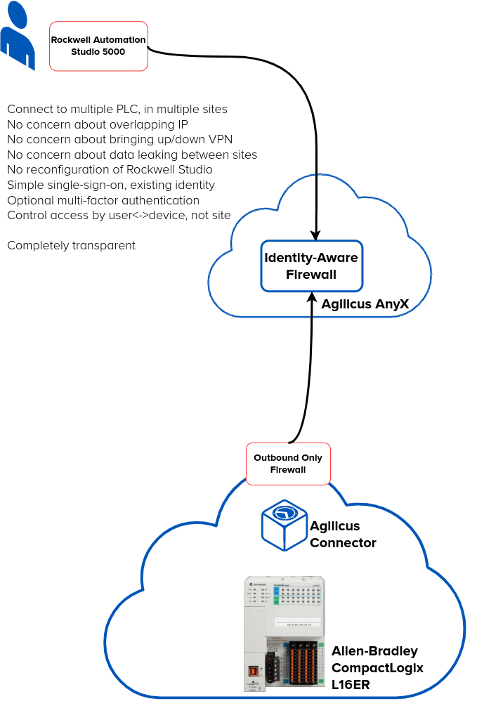
In this guide we show setup and interoperability between the Agilicus AnyX platform and Rockwell Automation’s Studio 5000 with RSLinx. This allows a PLC engineer to remotely support multiple sites, multiple customers, using their existing tools and setup. No VPN, no changing of IP’s. Connect to multiple customers simultaneously.
Customers get increased security, simple single-sign-on authentication with multi-factor, and a full audit trail. Permissions can be assigned (and audits can be observd) on an individual PLC basis, rather than an entire VPN or subnet.
For the example setup we have:
- Windows PC running Rockwell Studio 5000 (v29)
- CompactLogix 1769-L16ER
- Micro850 2080-LC50
- Raspberry Pi (serving as the Industrial PC / IPC)
The setup is such that the PLC are on a separate non-routable segment. The Raspberry PI is dual-homed, serving the PLC subnet and the connection outbound.
There is a highly restrictive firewall between the Raspberry PI and the Internet: it only allows outbound connections, on port 443, to the Agilicus AnyX platform: no inbound, no arbitrary outbound.
The operator will see no change on their laptop.
They launch RSLinx Classic0 from their start menu as normal. If they have not authenticated recently, a browser will popup to force a sign-in against their corporate identity provider (e.g. Microsoft Azure or Google Workplace). The Rockwell Automation software suite, Studio 5000, will then function as normal for all PLC viewing and programming.
Example Setup
User Desktop: Launcher Install
There is a one-time thing the user must do on their desktop to enable the Agilicus Launcher. No administrative privilege is required, and the configuration and software will automatically stay up to date.
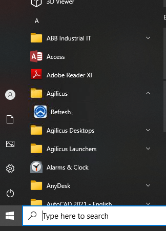
The user must open the Profile web page (https://profile.__MYDOMAIN__). From here they will download a binary and run it, it will sign-them in via the browser. At this stage, a new start menu item (Refresh) is present. Complete instructions are here.
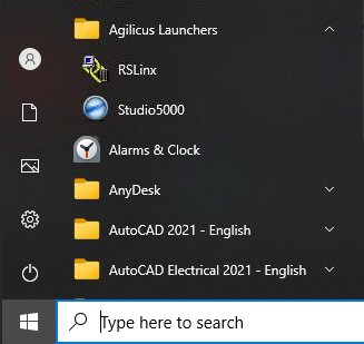
Once the Launcher is installed, a ‘Refresh’ icon will appear, as well as an icon RSLinx Classic. Launch the software from the icon as normal.
Agilicus AnyX Configuration (https://admin.__MYDOMAIN__)
- If not already done. Deploy the Agilicus Connector on your Raspberry Pi or other IPC
- Create a ‘Network’ resource for each PLC in the Agilicus with optional hostname creation (optionally make a Resource Group per site containing all Network Resources )
- Create a Launcher RSLinx Classic assigning the Network hosts resources, Associate resource members for the launcher.
At this stage, if your RSLinx has previously seen the PLC, it will be working, otherwise we can enter them manually as below.
With this complete, you can launch RSLinx and observe the first time you will see a browser open and be prompted to sign in. On subsequent launches it will have cached credentials.
Sample Project, CompactLogix 1769-LER, Agilicus Setup
First we do the networks (PLCs are each Network Resources):
- Add network Name (the name you will refer to the PLC in the Agilicus front end).
- This should be valid lowercase hostname in syntax
- Hostname/IP.
- Here the default behaviour would be to specify the IP address. If however this internal IP address is used and overlaps with multiple different sites, it is recommended to create an Adhoc hostname that has significance eg: compactlogix.
- The host name does not need to exist in the public DNS system, it will be used exclusively within the Launcher environment
- For PLCs having overlapping IP addresses across multiple sites, we can specify unique hostnames for each resource and select the unique Connector name to which they should be routing.

- In this environment, RSLinx can open two PLC resources that are labelled plc-site1 and plc-site2 in the Network Resource panel.
- Each PLC, using the same internal IP address, at different sites, can be reached individually via their hostnames which are routed via different connector to their specific local network segments.
- In this case, site1 PLC hostname would be configured in RSLinx as “PLC1.siteA:EIP”, and similarly site2 PLC could be reached via the hostname “PLC1.siteB:EIP”
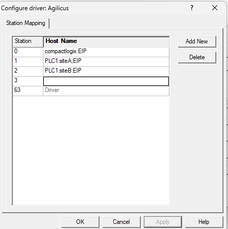
- Port. 44818, standard for Allen-Bradley PLC
- Override IP. The actual local IP address of the PLC that the hostname should map to
- Via Connector: The connector through which we wish to route to reach the PLC
At this stage we will create the Launchers:

Create a launcher for RSLinx:
Name: RSLinx
Command Path: C:\Program Files (x86)\Rockwell Software\RSLinx\RSLINX.EXE
Requires Interceptor: set
Require Elevated: set
Custom, Delayed Init: set
Resource Members: The network resource name representing every PLC host network resource previously created and that we wish to reach with this specific launcher instance. This can be a list of individual Network Resources, or a Resource Group.
At this stage we should assign permissions. For a larger scale, we recommend a Group for the users (so the permissions are assigned once, and users are later added/deleted from the Group). For a larger number of sites we recommend a Resource Group (so e.g. 1 Resource Group per site, or per type of PLC, or per job function, something of this nature).
- Assign permission to Launcher
At this stage, on the user desktop, you can run ‘Refresh’ or, install the Launcher for the first time, and RSLinx icon will appear in the Agilicus Launcher subfolder from the Windows Start menu
We can now launch RSLinx Classic from Agilicus Launchers -> RSLinx
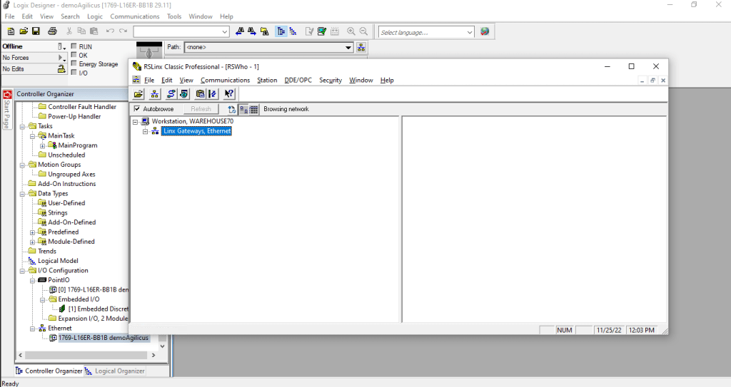
In RSLINX, Communications -> Configure Drivers
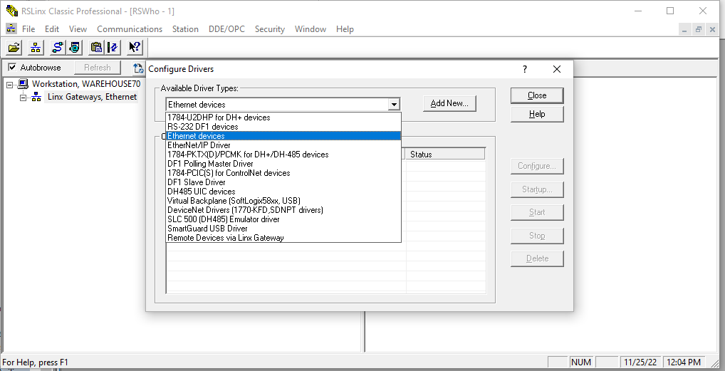
Select Ethernet:
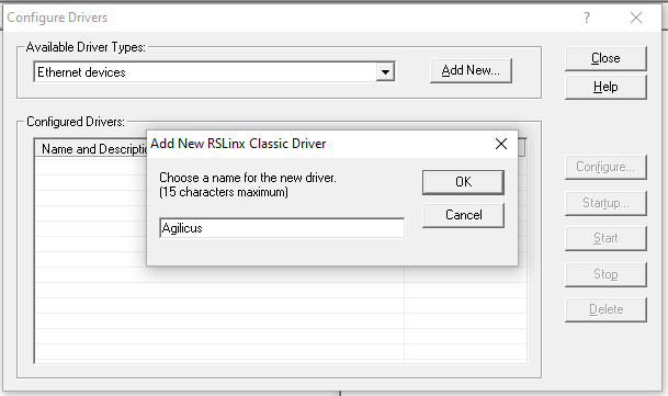
Enter the hostname AS DEFINED in the Network Resource “Hostname/IP”. (eg: PLC1.siteA), and add “:EIP” to specify the TCP port 44818 of EthernetIP should be used for this device.
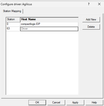
Apply the change.
The Agilicus, Ethernet driver will now probe the configured hosts, and it will add the device.
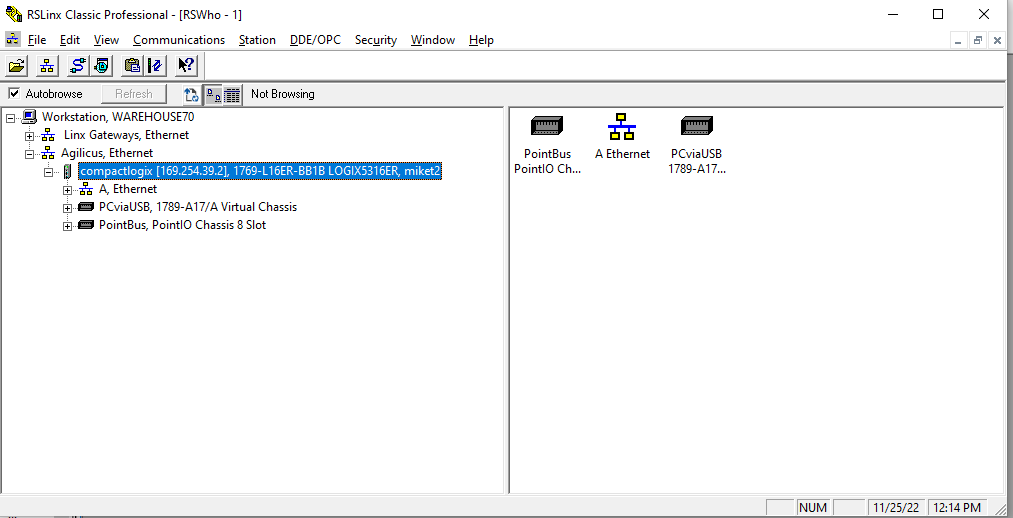
The Communications -> Who Active screen will now present the newly configured driver:
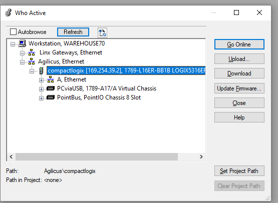
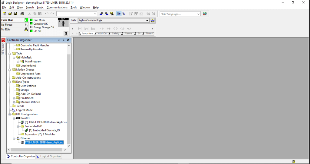
You can now run RSLogix500 or Studio5000 and set the project path for this device:
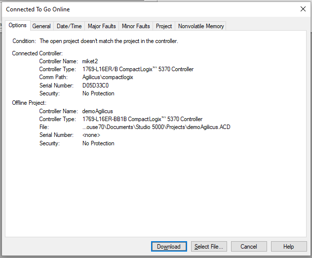
Download the controller configuration to the project.
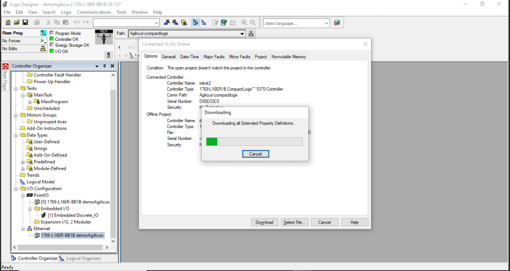
The PLC is now online and in Run Mode.
